


USB Type-C technical parameter diagram
Time:2023-09-29
Views:598
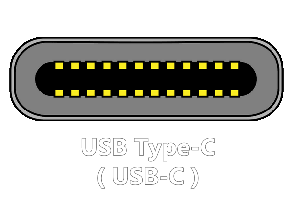
USB Type-C technical parameter diagram
USB Type-C is often found in a variety of electronics due to its own powerful features. This interface combines data, power and video in a single connector port; USB Type-C supports USB 2.0, USB 3.0 and USB 3.1 and offers alternate (Alt) mode options, such as DisplayPort for video; USB Type-C introduces 15W of inherent power capability and up to 100W of enhanced power capability when adding USB power transfer ( USB-PD) with up to 100W of enhanced power capacity; the interface introduces a smaller, thinner, and more robust jack capable of supporting data rates up to 20Gbps (for USB 3.2 specification, 3.1 specification meets 10Gbps).
USB-C simplifies connecting devices from the user’s standpoint. The connector is non-polarized, allowing the cable to be inserted either way up; hence, the USB-C connector now has 24 pins to cater for the large number of power and data connections required to support USB 3.2, USB4, and USB Power Delivery (PD), and to allow backwards-compatibility with USB 2.0.
In addition, the interface is bidirectional, allowing the cables to have the same connector at each end and permitting connected devices to act as host or device or as power consumer or supplier.
The USB Type-C interface offers 6 major advantages:
1) Full-featured: simultaneous support for data, audio, video and charging, laying the foundation for high-speed data, digital audio, high-definition video, fast charging, multi-device sharing, one cable can replace the previous multiple cables.
2) Reversible: similar to the Apple Lighting interface, with the same front and reverse side of the port, making it easy to use.
3) Bi-directional transmission: data and power can be transmitted in both directions.
4) Backward compatible: through the adapter, it can be compatible with USB Type A, Micro B and other interfaces.
5) Small size: the Type-C interface size is 8.3mm x 2.5mm, about 1/3 of the USB-A interface.
6) High speed: compatible with USB 3.1 protocol can support up to 10Gb/s data transfer.
USB-PD communication description
USB-Power Delivery (USB-PD) is a protocol specification that supports up to 100W of power transmission and data communication in a single cable; USB Type-C is a new reversible USB connector specification that can support a range of USB 3.1 (Gen1 and Gen2), Display Port and USB-PD, etc. The USB Type-C port can support up to 5V/3A by default; if USB-PD is implemented in it, it can support 100W of power (20V/5A) as defined in the USB-PD specification, so USB Type-C port does not mean it supports USB-PD; USB-PD appears to be just a protocol for power transmission and management protocol, in fact it can change the role of the port, can communicate with the active cable, allowing the DFP to become a powered device and many other advanced features, so devices that support PD must use the CC Logic chip (E-Mark chip).
Three current modes for USB Type-C:
The current detection and use function is added in USB Type-C. Three new current modes are added: default USB power mode (500mA/900mA), 1.5A, 3.0A; the three current modes are transmitted and detected by the CC pin, and for DFPs that need to broadcast current output capability, they need to be realized by different values of CC pull-up resistor Rp; for UFPs For the UFP, the voltage value on the CC pin needs to be detected to obtain the current output capability of the other DFP.
DFP is a USB Type-C port on the host or hub that connects to the device, UFP is a USB Type-C port on the device or hub that connects to the DFP on the host or hub, DRP is a USB Type-C port that works as either a DFP or UFP, DRP switches between DFP and UFP every 50ms in standby mode. DRP switches between DFP and UFP every 50ms in standby mode. When switching to DFP, the CC pin must have a pull-up resistor Rp to VBUS or output a current source, and when switching to UFP, the CC pin must have a pull-down resistor Rd to GND. this switching action must be done by the CC Logic chip.
This action must be performed by the CC Logic chip.
The concept of DRP/DFP/UFP:
The data transmission has mainly two sets of differential signals TX/RX, CC1 and CC2 are two key pins with many roles:detecting connections, distinguishing between positive and negative, distinguishing between DFP and UFP. Configure Vbus with two modes of USB Type-C and USB Power Delivery.
Configure Vconn: When there is a chip in the cable, a CC transmits the signal, a CC becomes the power supply Vconn. configure other modes, such as when connecting audio accessories, DP, PCIE when the power and ground are 4, which is why it can support up to 100W.
DRP (Dual Role Port): DRP can be both DFP (Host) and UFP (Device), and can also be dynamically switched between DFP and UFP. Typical DRP device is a computer (computer can be used as a USB host, can also be used as a device to be charged, with OTG function of cell phones (cell phones can be used as a device to be charged and read data, can also be used as a host to provide power for other devices or read UDP data), mobile power (discharge and charge can be through a USB Type-C, that is, this port can discharge and charge).
Typical DRP implementation of USB Type-C:
The concept of CC pin:
CC (Configuration Channel): This is a new key channel in USB Type-C, its role is to detect the USB connection, detect positive and negative plugging, data between USB devices and VBUS connection establishment and management, etc..
There is pull-up resistor Rp in CC pin of DFP and pull-down resistor Rd in UFP. when not connected, there is no output from VBUS of DFP. When connected, the CC pin is connected and the CC pin of DFP detects the pull-down resistor Rd of UFP, indicating that it is connected, DFP turns on the Vbus power switch and outputs power to UFP. And which CC pin (CC1, CC2) detects the pull-down resistor determines the direction of interface insertion and switches RX/TX by the way.
Resistor Rd = 5.1k, resistor Rp is an uncertain value, according to the previous figure to see the USB Type-C has several power supply mode, rely on what to screen? On the value of Rp, Rp value is different, the voltage detected by the CC pin is not the same, and then to control the DFP side of the implementation of which power supply mode.
Note that the diagram above shows two CCs, but in fact there is only one cc line in the cable without the chip.
![]()
By HornmicLink_Bob Kuo @230929 09:55


 ChatNow
 Henry Xu